Showing posts with label Kyle Hayes. Show all posts

Tuesday, June 5, 2012

A4 - Group 8: Xue, Hayes, Jiang


Background


The Bridge Design Project primarily used West Point Bridge Design Software and K’nex to show engineering students the basic concepts about how to build a bridge and how the design affects its performance. West Point Bridge Design helps students model, test, and optimize a steel highway bridge based on realistic specification, constraints, and performance criteria. Below is the link to a blog from a member of group 8 indicated their feeling of West Point Bridge Design after using only a few time.


During the process of learning how to interpret the data given by West Point Bridge Design, some ideas of design had already been getting rid of because they could not pass the truck test, see below.  
Figure 1: A successful design in West Point Bridge Design


If a bridge could not pass a simulated test how could that design and structure ever be feasible enough to make a prototype. The designs which passed the test, needed to improve because the high cost and inability of the K’nex pieces to be that exact size or lay at that angle. Using the data gather from West Point Bridge Design we could now start building plausible physical bridges out of K’nex.

            K’nex behave more closely to a real bridge than compared with West Point Bridge Design. It has to be built piece by piece from nothing. There’s no sample bridge support be given like one West Point Bridge Design. Thus, building a K’nex bridge a feasible idea and blueprint is needed, a blueprint that could be found on a West Point Bridge Design model that passed the truck test. West Point Bridge Design tests showed that a bridge with top and bottom trusses is more stable than that only with one side of truss, due to the more options the weight has to distribute. Thus our initial, 24 inch K’nex bridge was born.


Figure 2: First design of K’nex bridge, 24” span


The goal of this project is designing the most serviceable K’nex bridge by truss analyzing. The ideal bridge would be loaded maximum loading with the lowest cost after several forensic and static analyses.

Design Constraints


            The bridge span for the final design is a thirty-six inch minimum. The width of the final design must be greater than three and a half inch. The bridge must be a feasible prototype design to a real bridge, meaning that a scale car must be able to fit through the bridge, the constraint for this was that a three inch by two inch tube be able to fit continuously through the span of the bridge.

Design Process


             The goal of our bridge is to design a most severable bridge with the lowest cost. Our 24” inch bridge was mostly build using the 1.125” inch chord. In the final bridge, the bridge size is increase, so we use 3.375” long chord instead of the 1.25”one. By testing how different angles work in the bridge. By the calculations we got the middle section is the part which undergoes most of the tension, so we change the middle part to smaller truss, so it can separate the tension of the loads. At the fist design we made the end members very strong as they must negate the force and are under as much force as the middle ones, so we get rid of some chord to short the cost. The original design also had numerous non-fixed member connecting the two halves. This was untimely the reason the first bridge failed, the non-fixed connection allowed the bridge to twist and lean and cause the first bridge to fall over on itself due to too much leaning

The double truss structure was an idea taking from the individual bridge design portion of the project. In the individual project one of designs was to have a single truss structure bridge, the other was a double structure bridge. The data gather by West Point Bridge designer showed that the double structure had a more stable shape and only increase the cost by a minimal amount, thus giving us our basic shape. Our final shape and size of the bridge is decided by testing physical model and data obtained thought experimenting on the bridge designer website. Using the data we gathered in latter we were able get the data we need and improve the bridge without test our real bridge and having to go through rigorous trial and error. This also helped avoid wearing down the pieces and accidentally damage and weaken them avoiding possible unwanted failures but to the condition of the pieces. Of course theory can only go so far so physical test must be done as well. We did test our bridge use reams of paper (500 pages of standard computer printer paper) and book. Upon weighting the books on a scale we found our bridge could hold a load a bit above 30 pounds. It is a good number base on the low cost of the bridge.       

Final Design


            The final design was a top and bottom truss bridge, which used a fair number of pieces, more than the bare minimum but far from excessive to keep the cost to a minimal. The connection between the two halves was by fixed connection on the top, middle, and bottom rows. It also had a few non fixed connections spanning across the halves, this was done to save money and through testing was found that having so few would not compromise the bridge strength and cause it to possible twist or lean to one side when weight was added leading to a premature failure. The idea behind the top and bottom truss is that the more connections there are the more ways the weight’s force can travel, having both a top and bottom mean that the main area the weight will be focused, that being the center and central top have more options to escape to and the weight will be distributed to the top and bottom and could be sent to the end in more options. This design did work much better than just having a top or bottom truss in testing thus it was chosen as the favorable shape.

Figure 3. Final Design in Final Test
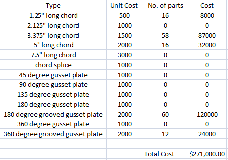
            Below is a table of the parts, number of the parts and the cost, with the total piece count and cost at the bottom of their respective columns. Final piece count was 196 and the final cost was $307,000.


Table 1: Bill of Material


Testing Results


            The load at failure of the final design was 17.0 pounds. The failure was around the center area and towards the bottom of the bridge and was the result of two grooved gussets being pulled apart as shown below. A very small and simple failure that resulted in the bridge remaining whole and simply falling through the span rather than violently being ripped apart and being almost completely destroyed in failure. In terms of bridge failures this was a very calm and more favorable break.


Figure 4. Failed Connection

Conclusion of Results


            The final test did not behave as predicted and did not behave like any of the previous tests. In terms of the load the final design only held 17.0 pounds where the final version of the twenty-four inch span held 34.0 pounds. The final design only preformed half as well as the twenty-four inch span model meaning the design did not improve but rather became worst. The predicted load was forty pound, which was on the high side, thought multiple test on the final design prior held an average of around thirty to thirty-five pound, in which forty pound would not be too far off. This final test was most likely the fluke of all the testing and may be due to how the bridge failed.

            In many of the prior test and the twenty-four inch span test failed very close to the ends of the bridge due to all the surrounding members being pulled out of the gussets and the center falling straight down, usually resulting in a clean break leaving the bridge in two or three solid pieces and no single loss member or gusset. In the final test however, the grooved gussets pulled apart from each other around the center of the bridge, leaving it whole but with pieces not fixed together. The image below shows where the bridge normally failed (in blue) and where it failed in the last test (in red).


Figure 5. Usual Failed Connections and Final Test Failed Connections


The bridge only failed in the center area and because of grooved gussets being pulled apart once during all the prior testing. The conclusion as to why it failed like this is either due to a missed defect prior to testing or some small difference in this test that did not occur in the previous tests. Regardless, the final test did not behave as the previous test had shown, but that is just how things work out and so long as we can learn and understand from this failure there is always room for improvement in the future.

Future Improvements


Given the chance to modify our design to another version, the largest change would be to build a bridge with only one truss. The two truss worked but when it counted seemed to fail up to its standard and the extra pieces added a fair cost to the bridge, making a one truss bridge would save money and that saved money could be use to add extra support to critical areas such as the center and ends and would allow for more cross connections between the two halve stabilize the bridge, and we feel confident that a one truss bridge could hold more than the final test did and even save money.

Week 10 - Kyle Hayes


Last week in class we held our final test as every group tested their final design showing all they have worked for these past few weeks and what was the most cost effective design. Our bridge only held 17 pounds, which was a bit of a letdown as prior testing showed that it was able to hold roughly around 30 pounds. As to why the bridge preformed this way I am not sure, perhaps the bridge was not properly constructed again after testing the night before, or perhaps it was just a fluke, either way nothing we can do, that’s just how the bridge behaved. On the bright side the bridge only cost $307,000 and was still decently cost effective.

      I felt that this project has been worthwhile and it definitely helped be learn about the creative process of how a design evolves and grows bases on experimentation and, trial and error, and observing failure and individual components. My understanding of computer based programs to test designs and components has vastly improved and understanding how this data can be interpreted and used to make even small adjustments to the bridge that dramatically improve the performance. The most worthwhile aspect was not the design process or the computer and data skills but learning the smaller more complex mechanics that might be over looked until you come across them. The perfect example being how the weight capacity is determined by the gusset strength which is affected by numerous factors such as the pressure exerted on the gusset member connection by the adjacent connection and in real bridges the age, physical condition and the welding of these connections, each a small detail but will drasticly affect the connection and capacity.

The greatest benefit for me was how the class was handled. The class was more relaxed, there was not the stress of crunch time and you could test variable and design at your leisure, you could put as much effort as you want and that help me with motivation. Not feeling required and pressured from work made it feel less like more and more of a pleasant hobby and made me more motivated to learn and try to do the best not for a competitive achievement of placing high but for self achievement to do my best and feel satisfied of the effort put into the project.

The two least beneficial aspects for me were the method of joints project for A3 and the blog posts. The method of joints was interesting and it was beneficial and I will most likely have to use it in the future so it nice to start learning now but it was tedious and felt somewhat pointless when there was an online program that could do it for more complex bridge. The reason I did not like the blog posts was because I found it easier and more clear and helpful when we used the notebook last term to record our data and progress.

I don’t feel like there is much need to improve for this section, it was clear, simple yet challenging, and taught us the basic of bridge design and how and why they work and react as they do. This section was exactly what it said it was going to be and what it was going to teach us. The only thing is that I felt that this section was handled and felt different than most of the other engineering 103 sections and I agree with the idea that this class might be better if it were an alternative choice the NXT module in engineering 102.

This week in class we will be our last class and we will be wrapping up the term and the truss bridge design project and just go over what we learned, the process, and how we felt about the class.

-   Kyle Hayes

Tuesday, May 29, 2012

Week 9 - Kyle Hayes


Last week we finished our work on the static of bridge design using the method of joints to solve for the forces in the members. We also worked on finishing up and testing the final design of our bridges, testing numerous small factors and detail to minimize cost and increase strength. Small changes such as changing the length of pieces and changing the gusset type.

What I have learned about bridge designing is that the maximum capacity of the bridge is determined by the maximum pull out force of a gusset and that the tension can be reduced in a member via the force distributing to adjacent members. I learned that the point of failure is at the gussets and usually occurs at the ends as they have to take all the weight to disperse it to the ground. Also I have discovered through testing that having fixed connections are important as free ones cause the bridge to be able to shift and bend and will cause a easy quicker failure. I learned that hollow bars are better to use then solid bars as they have more give and flexibility, and that the most stable shape is the triangle so it is essential to the design of a truss. Finally I learned that the cost of a bridge is directly proportional to the weight of the bridge. There were many other things that I learned but this are some of the most important

This week in class we will be having our in class competition to see what group had the highest strength to cost ratio. All are work and testing comes down to this.
    -   Kyle Hayes

Monday, May 21, 2012

A3 - Kyle Hayes


Ends

   ΣFX = 0:   FAX = 0

   ΣFY = 0:   -10lbs x 1ft + FEY x 2ft = 0

FEY = 10/2 = 5lbs

FEY = 5lbs

FAY = -10lbs + FEY = 0:   FAY = 5lbs

FAY = 5lbs


Joint A

   ΣFY = 0:   TAB sin(45) + FAY = 0:   TAB = -5/sin(45) = -7.07lbs

                TAB = -7.07lbs

   ΣFX = 0:   TAB cos(45) + TAC = 0:   TAC = 7.07 cos(45) = 5lbs

                TAC = 5lbs


Joint B

   ΣFY = 0:   -TAB sin(45) + TBC sin(45) = 0:   TBC = -TAB sin(45) / sin(45) = 7.07lbs

                TBC = 7.07lbs

   ΣFX = 0:   -TAB cos(45) + TBC cos(45) + TBD = 0:   TBD = -7.07 cos(45) - 7.07 cos(45) = -10lbs

                TBD = -10lbs


Joint C

   ΣFX = 0:   TBC sin(45) + TCD sin(45) -10lbs = 0:   TCD = [10 – 7.07 sin(45)] / sin(45) = 7.07lbs

                TCD = 7.07lbs

   ΣFY = 0:   -TAC – TBC cos(45) + TCD cos(45) + TCE = 0:   TCE = 5 – 7.07 cos(45) – 7.07 cos(45) = -5lbs

                TCE = -5lbs


Joint D

  ΣFY = 0:    -TCD sin(45) – TDE sin(45) = 0:   TDE = -7.07 sin(45) / sin(45) = -7.07lbs

                TDE = -7.07lbs


Joint E

   All tensions around joint E are already solved for.

My Analysis Diagram


Bridge Designer Analysis


To make sure the hand analysis corresponds to the Bridge Designer, the lengths of the members and the angles must scale to each other. So that all angle are the same between the hand and Bridge Designer analysis. For the members it is just important the relative size to one another is kept the same. If two pieces are the same length as each other than those two corresponding pieces on the Bridge Designer must be the same length. If one is twice the size of the other, than the corresponding piece on the Bridge Designer must be twice the size of the other.


K'NEX
Bridge Designer Analysis


The K’NEX joint test page showed that the pull out for required to remove a member from a joint increase with the more members attached to that joint, it also increase more if it is symmetrical. This test tells us that the average max limit of tension of a member can be 37lbs before the connecter is almost guaranteed to fail, useful information as any member nearing this tension amount must be adjusted and will most likely fail first. We can use the fact the more members per connector increases the tension required to remove the member to strengthen our connection. Where ever there is a spot nearing this maximum tension amount we can add a member that will have a vector force in the same direction as the member nearing the max tension to increase capacity. To explain a bit more clearly, the example only had three of the five slots of the connector use, the other to slots, the ones on the end would not contribute to increasing the strength though as they were only in the x direction and thus can only hold and x direction vector force, but the three that were used either only had a y vector or had a component of them that was in the y direction. This is why adding members increases the tension needed to pull it out, because it is not just that member being pulled in the y direction but some of the pull is being sent to the other member whose vector is in both the x and direction.
    - Kyle Hayes

Week 8- Kyle Hayes


Last week we practiced how to calculate the force on each member of the truss using method of joints by calculating it for a low load simple 7 member bridge. After doing the calculations and following the video tutorial we verified it using Bridge Designer online, and then we used Bridge Designer on our K’NEX design to help analyze the tension and compression of each member which will be used to improve our design as we near the final weeks.

I feel that this method is good for calculation basic tension, but must less reliable when there are many loads that are always moving and changing value rather than fixed to just one joint. Also like many of the other method we used this only calculates for perfect conditions, no live load, no wind or other force, and the members and gussets are perfect fit and perfect condition. So yes, it is a useful tool but not sufficient enough and reliable enough to count for a real bridge.

The one other thing I would like to analyze is the tension of the gussets. What is the max strength of the member-gusset connection, and the strength limit of the two grooved gussets stuck together as they seem much weaker and tend to fail more often than the member-gusset connection in my experience.

This week in class we will be using the data collected from Bridge Designer for our K’NEX bridge and fix our design based on adjusting high and low tension points of our design.

Tuesday, May 15, 2012

Week 7 - Kyle Hayes


Last week we tested our two foot span design, our design was two feet long but the span was just shorted so we were forces to add a bit to the length, but over all I don’t think that changed much of the design or the strength. Our bridge’s cross sections were mot all fixed positions so when the weight was added the non-fixed parts were bowing and moving and it caused the bridge to twist sideways and fail because more the sides leaning too much.

For the K’NEX the numbers I would like to know are the amount of force on the bars as the weight is loaded from the middle, as this would help determine the strength limits of that piece and where can be improved and where can be reduced.  My idea for calculating them is to use trig to see how the forces get spread based on its angle but I know that it is more complex than just that.

This week for class we will be using our two foot span bridge and the information we gained from the test to make a three foot span design.

-          Kyle Hayes

Monday, May 7, 2012

Week 6 - Kyle Hayes


This week we built and tested our individual designs to see what was the best and what were good components of the design. Upon reaching l design and testing it, we found that the ends were the weakest and failed after a few pounds and the grooved gussets were pulled apart easily so to make it stronger at the gusset and cheaper we will use non grooved gussets and to help with support we made the pieces between the gussets shorter. This will make it more stable, compact, and cut cost, but this will require more pieces which will increase the cost a bit but not over the original design.

I feel the same about what I stated last week about WPBD and K’NEX, both are fairly different and the K’NEX is much more restrictive. The difference with Steel and the K’NEX is that the steel would allow for customization of length and gussets and thus give more options it rather than just ten fixed pieces. At the same time give many more options and starts to be a bit like WPBD in that you have price dependent on weight rather than piece and you have to pick solid or hollow and the length and it becomes more complex to figure out the bridges strength.

Next week we will be testing our K’NEX design for the two foot span, followed by going back to improve our design and prepare for the final test with the three foot span.
    - Kyle Hayes

Tuesday, May 1, 2012

A2 - Hayes


The reasoning of my shape is because I like the results I have gotten in WPBD using a top and bottom truss. Although I do wish the top was more arch like but I found it difficult to make but given more time and experimentation I believe it will become more arch like in the future. It was shaped to be fairly condensed using short pieces as they were more stable in testing also it is not too expensive as the longer pieces are and it does not require too many gussets as if done using shorter length peices.
Side View

 Top View
 I felt it was unneeded to put the lenghts and dimensions as it is color coded and each color has a fixed length. White: 1.25", Yellow: 3.375", Red: 5"

The gussets are blue dots and are all made of two 180 degree grooved gusset plates put together so the cross bars can be added to attatch the two sides. the only exception is there are 5 gussets per side that are 180 degree grooved gusset plate and 360 degree grooved gusset plate together, these are used in the middle where the gusset has bar located to the top, bottom, and both side.


Height: 6.77"
Lenght: 25.25"

Cost Table


There were not many changes as I wanted to keep it as simple as possible but some of my changes are as followed. The base was made of five red bars, I changed to six yellow as I feel the shorter ones will be more stable and offer more connections on the upper level. Second the highest level was just like the middle but I changed it to be like the bottom in hope that it would be more stable and also to cut cost. Also the bars that connect the two sides was red but I changed it to yellow bars as it would condense it and also cut cost a bit. These were the major changes.

I learned that some time material is predetermined in length and thus options are limited and some designs require tweaking or may not be possible.
   - Kyle Hayes

Week 5 - Kyle Hayes


I was sick and unable to attend class this week and therefore I am unable to provide my experience, however I did go over the slides and look up the constraints and pieces and cost of the pieces and I feel that I have a fair understanding of what happened without being there.

The K’NEX will be more restrictive, there is only one material, and there are predesigned lengths and thicknesses, where on WPBD this could be customized. Similarities are obviously they will both test designs and help analyze information; WPBD will give values where as the K’NEX will only tell us that it broke here therefore it needs to be strengthened. WPBD is under perfect conditions and is only a simulation but K’NEX will be a real prototype and will not work perfectly, there will be many small factor that affect each individual piece as each piece is different. I feel that unexpected results may occur with the K’NEX due to all the small factors and the lack of full customization. The K’NEX design will be much more challenging due to the constraints and predetermined lengths and it will much harder to lower cost as you would have to change the design and shape rather than the material thickness and type. Overall I find the two to be fairly different, they both test bridges but have very different styles of design and testing.

Next week we will begin using the K’NEX and start with our individual designs which will be tested and then what we individually gathered will come together in the end to form one final team bridge.

-          Kyle Hayes

Monday, April 23, 2012

Week 4- Kyle Hayes


This week we gathered our group’s designs and tried to find the best parts of the three and create an even better bridge. we did manage to cut a few thousand dollars in cost, down to around$240000. We wanted to make a bridge that was only either a top truss or a bottom truss which did work and was a bit cheaper that of a bridge with a top and bottom truss. In my personal opinion I prefer the top and bottom truss bridge, although more complicated I found it to be less challenging to make and might give more strength on the actual model. With a bit more experimenting I came to the conclusion to use only hollow bars because they are cheaper and always stronger, the reasoning was explain be a TA that it is because it has a higher moment of inertia and thus will hold more weight. Also that when the bridge is is arched the weight wwill be distributed better and thus arch trusses can suport more weight.
WPBD is a very useful tool to make bridge design and test tension and compression. However I do not like using it for a model for the K’NEX competition. The K’NEX will not be joined perfectly like on WPBD also the K’NEX are all solid made of the same material and can’t be thickened so the fact that these can be changed and the goal in WPBD is to make the cheapest bridge not cost to strength ratio. If the bridge in the model is made solid, out of the same material, and same thickness then this can be more useful but they way it is being used is not very accurate for this assignment.  Two other problems with WPBD are there are no other forces, such as wind or age and rust; WPBD is only for the ideal conditions. The second is that the load added is fix, the weight added is limited to the one truck, which tell if it held or fell and the tension each piece was at, if more weight could be added and to a fixed location it would actually provide a defined weight limit and the cost of the bridge which would give a ratio used in our competition. WPBD is a very nice tool to make designs and see if there geometrically stable but not great when some conditions are fixed and real life is not ideal.

Next week we will use the knowledge gained by the guest speaker and use that to help with the next bridge design. We will also try a final analysis using WPBD before we start building the K’NEX model based on all the information gathered.

         - Kyle Hayes

Tuesday, April 17, 2012

Week 3 - Kyle Hayes


This week I experimented with the two cross section types, bar and tube. I found tube to be more cost effective. Also I tested the three types of metals, CS, HSS, and QTS. I found HSS to be the most cost effective, it was much cheaper than QTS and only slightly more than CS but much stronger. I also came to the conclusion that condensed bridges are less expensive and perform better to less tension on such long piece that would have to be thicken to hold that same weight, so short and thin is better thick and long. With WPBD it was easy to make changes, test, and find the data on how to adjust from there. One thing I learned is that an easy way to be cost effective it to make some few important areas just a bit stronger will allow you to reduce many other areas allowing the bridge to still hold but still reduce the cost. Last I did some research into how trusses designs work.

My research of truss bridges has shed light on to why they are made with triangles and what the more common styles that are used, many have more of an X crossing rather than a crossing that goes to the left or right like /|/| / or \|\|\ . Also I learned that while truss bridges are very effective over short to medium spans, arch bridges seem to be more efficient and hold more weight when compared to the truss, so trusses that have an arch shape or angled on top tend to be better. In my research I found that many trusses are top trusses rather than bottom trusses, the reason being that the weight gets distributed downward and out to the ends better that way. These mean that the middle where the load is farthest from the distribution point at the ends and at the ends are the areas that undergo the most force and undergo it for most of the time meaning that these areas must be more enforced than the rest of the bridge.

What were going to do this week is to compare our bridge data and try to combine the best aspects of each and make them work together as best as possible. This week will mostly be a lot of analysis and much more testing in WPBD to see what can still be improved before we move to models .

My three questions will be:
What are the pros and cons of a truss bridge to other short to medium length bridges?
What is the strongest load design for a truss, normal or arched? Truss on top, bottom, or both?
When bridges fail what is the most common reason why and what is the area that fails?

-          Kyle Hayes

A1 – Hayes


My bridge was designed with two main goals, make it compact and spread the tension into two parts, top and bottom, I felt this would hold the weight and make the bridge light as can be.
Bridge in Drawing board mode

With Truck in view mode


#          Material Type  Cross Section   Size (mm)        Length (m)       Compression Force      Compression Strength            Compression Status     Tension Force  Tension Strength          Tension Status

1          HSS     Hollow Tube    200x200x10    4.00     1441.03           1946.41           OK       0.00     2490.90           OK

2          HSS     Hollow Tube    170x170x8      4.00     1213.09           1234.91           OK       0.00     1699.06           OK

3          HSS     Hollow Tube    100x100x5      4.00     213.27 273.05 OK       0.00     622.73 OK

4          HSS     Hollow Tube    130x130x6      4.00     437.99 587.81 OK       0.00     975.38 OK

5          HSS     Hollow Tube    80x80x4          4.00     57.94   114.70 OK       153.82 398.54 OK

6          HSS     Hollow Tube    110x110x5      4.00     261.91 346.95 OK       0.00     688.28 OK

7          HSS     Hollow Tube    80x80x4          4.00     50.05   114.70 OK       170.08 398.54 OK

8          HSS     Hollow Tube    130x130x6      4.00     437.66 587.81 OK       0.00     975.38 OK

9          HSS     Hollow Tube    110x110x5      4.00     219.77 346.95 OK       0.00     688.28 OK

10        HSS     Hollow Tube    170x170x8      4.00     1165.06           1234.91           OK       0.00     1699.06           OK

11        HSS     Hollow Tube    200x200x10    4.00     1412.05           1946.41           OK       0.00     2490.90           OK

12        HSS     Hollow Tube    200x200x10    4.00     1721.12           1946.41           OK       0.00     2490.90           OK

13        HSS     Hollow Tube    240x240x12    4.00     2225.39           2972.71           OK       0.00     3586.90           OK

14        HSS     Hollow Tube    240x240x12    4.00     2396.91           2972.71           OK       0.00     3586.90           OK

15        HSS     Hollow Tube    240x240x12    4.00     2439.16           2972.71           OK       0.00     3586.90           OK

16        HSS     Hollow Tube    240x240x12    4.00     2456.75           2972.71           OK       0.00     3586.90           OK

17        HSS     Hollow Tube    240x240x12    4.00     2382.71           2972.71           OK       0.00     3586.90           OK

18        HSS     Hollow Tube    240x240x12    4.00     2180.86           2972.71           OK       0.00     3586.90           OK

19        HSS     Hollow Tube    200x200x10    4.00     1658.65           1946.41           OK       0.00     2490.90           OK

20        HSS     Hollow Tube    170x170x8      2.83     1330.42           1409.88           OK       0.00     1699.06           OK

21        HSS     Hollow Tube    170x170x8      2.83     1288.17           1409.88           OK       0.00     1699.06           OK

22        HSS     Hollow Tube    190x190x9      2.83     0.00     1819.47           OK       2037.92           2135.62           OK

23        HSS     Hollow Tube    100x100x5      4.00     0.00     273.05 OK       576.13 622.73 OK

24        HSS     Hollow Tube    35x35x2          4.00     0.00     4.70     OK       71.25   86.53   OK

25        HSS     Hollow Tube    100x100x5      4.00     62.44   273.05 OK       84.42   622.73 OK

26        HSS     Hollow Tube    60x60x3          4.00     0.00     36.29   OK       199.77 224.18 OK

27        HSS     Hollow Tube    80x80x4          4.00     2.33     114.70 OK       266.11 398.54 OK

28        HSS     Hollow Tube    90x90x4          4.00     34.16   166.09 OK       262.97 450.98 OK

29        HSS     Hollow Tube    60x60x3          4.00     0.00     36.29   OK       217.75 224.18 OK

30        HSS     Hollow Tube    100x100x5      4.00     59.73   273.05 OK       95.92   622.73 OK

31        HSS     Hollow Tube    40x40x2          4.00     0.00     7.17     OK       82.63   99.64   OK

32        HSS     Hollow Tube    100x100x5      4.00     0.00     273.05 OK       559.33 622.73 OK

33        HSS     Hollow Tube    190x190x9      2.83     0.00     1819.47           OK       1996.94           2135.62           OK

34        HSS     Hollow Tube    200x200x10    2.83     1318.88           2143.16           OK       0.00     2490.90           OK

35        HSS     Hollow Tube    200x200x10    2.83     1379.71           2143.16           OK       0.00     2490.90           OK

36        HSS     Hollow Tube    60x60x3          4.00     0.00     36.29   OK       171.81 224.18 OK

37        HSS     Hollow Tube    60x60x3          4.00     0.00     36.29   OK       163.44 224.18 OK

38        HSS     Hollow Tube    80x80x4          2.83     0.00     206.83 OK       279.32 398.54 OK

39        HSS     Hollow Tube    100x100x5      2.83     397.96 401.36 OK       0.00     622.73 OK

40        HSS     Hollow Tube    90x90x4          2.83     0.00     266.95 OK       392.28 450.98 OK

41        HSS     Hollow Tube    80x80x4          2.83     0.00     206.83 OK       382.19 398.54 OK

42        HSS     Hollow Tube    90x90x4          2.83     0.00     266.95 OK       260.04 450.98 OK

43        HSS     Hollow Tube    80x80x4          2.83     131.58 206.83 OK       133.95 398.54 OK

44        HSS     Hollow Tube    80x80x4          2.83     140.37 206.83 OK       125.16 398.54 OK

45        HSS     Hollow Tube    80x80x4          2.83     108.21 206.83 OK       150.72 398.54 OK

46        HSS     Hollow Tube    80x80x4          2.83     157.14 206.83 OK       101.78 398.54 OK

47        HSS     Hollow Tube    90x90x4          2.83     0.00     266.95 OK       232.48 450.98 OK

48        HSS     Hollow Tube    80x80x4          2.83     0.00     206.83 OK       384.87 398.54 OK

49        HSS     Hollow Tube    90x90x4          2.83     0.00     266.95 OK       433.17 450.98 OK

50        HSS     Hollow Tube    110x110x5      2.83     438.88 475.64 OK       0.00     688.28 OK

51        HSS     Hollow Tube    80x80x4          2.83     0.00     206.83 OK       283.45 398.54 OK

52        HSS     Hollow Tube    140x140x7      2.83     0.00     950.00 OK       1103.61           1220.54           OK

53        HSS     Hollow Tube    100x100x5      2.83     59.14   401.36 OK       232.76 622.73 OK

54        HSS     Hollow Tube    120x120x6      2.83     560.34 650.14 OK       0.00     896.72 OK

55        HSS     Hollow Tube    90x90x4          2.83     215.51 266.95 OK       0.00     450.98 OK

56        HSS     Hollow Tube    75x75x3          2.83     0.00     137.10 OK       209.12 283.18 OK

57        HSS     Hollow Tube    120x120x6      2.83     608.03 650.14 OK       0.00     896.72 OK

58        HSS     Hollow Tube    120x120x6      2.83     546.39 650.14 OK       0.00     896.72 OK

59        HSS     Hollow Tube    90x90x4          2.83     248.66 266.95 OK       163.63 450.98 OK

60        HSS     Hollow Tube    90x90x4          2.83     170.12 266.95 OK       242.18 450.98 OK

61        HSS     Hollow Tube    120x120x6      2.83     542.53 650.14 OK       0.00     896.72 OK

62        HSS     Hollow Tube    120x120x6      2.83     625.84 650.14 OK       0.00     896.72 OK

63        HSS     Hollow Tube    75x75x3          2.83     20.38   137.10 OK       170.10 283.18 OK

64        HSS     Hollow Tube    80x80x4          2.83     176.46 206.83 OK       14.02   398.54 OK

65        HSS     Hollow Tube    120x120x6      2.83     538.54 650.14 OK       0.00     896.72 OK

66        HSS     Hollow Tube    100x100x5      2.83     102.26 401.36 OK       234.00 622.73 OK

67        HSS     Hollow Tube    140x140x7      2.83     0.00     950.00 OK       1057.52           1220.54           OK

68        HSS     Hollow Tube    120x120x6      2.83     575.47 650.14 OK       0.00     896.72 OK

69        HSS     Hollow Tube    120x120x6      2.83     592.00 650.14 OK       0.00     896.72 OK

70        HSS     Hollow Tube    100x100x5      5.00     146.01 179.21 OK       132.55 622.73 OK

71        HSS     Hollow Tube    100x100x5      5.00     139.89 179.21 OK       138.67 622.73 OK

72        HSS     Hollow Tube    120x120x6      5.00     239.76 368.26 OK       80.17   896.72 OK

73        HSS     Hollow Tube    90x90x4          2.00     0.00     337.72 OK       404.31 450.98 OK

74        HSS     Hollow Tube    220x220x11    4.12     0.00     2411.10           OK       2529.19           3013.99           OK

75        HSS     Hollow Tube    200x200x10    4.00     0.00     1946.41           OK       2367.23           2490.90           OK

76        HSS     Hollow Tube    200x200x10    4.00     0.00     1946.41           OK       2367.23           2490.90           OK

77        HSS     Hollow Tube    220x220x11    4.12     0.00     2411.10           OK       2516.28           3013.99           OK

78        HSS     Hollow Tube    90x90x4          2.00     0.00     337.72 OK       408.73 450.98 OK

79        HSS     Hollow Tube    120x120x6      5.00     229.38 368.26 OK       82.99   896.72 OK

80        HSS     Hollow Tube    130x130x6      3.00     665.55 716.45 OK       0.00     975.38 OK

81        HSS     Hollow Tube    30x30x2          3.00     0.00     5.11     OK       2.96     73.42   OK

82        HSS     Hollow Tube    130x130x6      3.00     675.96 716.45 OK       0.00     975.38 OK

83        HSS     Hollow Tube    110x110x5      4.47     0.00     296.32 OK       672.65 688.28 OK

84        HSS     Hollow Tube    110x110x5      2.00     497.04 556.90 OK       0.00     688.28 OK

85        HSS     Hollow Tube    180x180x9      4.00     0.00     1506.95           OK       1939.27           2017.63           OK

86        HSS     Hollow Tube    180x180x9      4.00     0.00     1506.95           OK       1935.83           2017.63           OK

87        HSS     Hollow Tube    110x110x5      2.00     497.70 556.90 OK       0.00     688.28 OK

88        HSS     Hollow Tube    110x110x5      4.47     0.00     296.32 OK       661.20 688.28 OK

89        HSS     Hollow Tube    200x200x10    8.25     0.00     1040.87           OK       1963.88           2490.90           OK

90        HSS     Hollow Tube    90x90x4          4.47     106.78 132.87 OK       95.29   450.98 OK

91        HSS     Hollow Tube    200x200x10    8.25     0.00     1040.87           OK       1955.00           2490.90           OK

92        HSS     Hollow Tube    90x90x4          4.47     105.89 132.87 OK       87.22   450.98 OK


The bridge change material and cross section type numerous times to see which was most cost effective. The original bridge was twice as tall; all the bars were condensed because after testing length strengths I came to the conclusion that shorter lengths were not only stronger but cheaper. The Truss on top had and extra layer but it was excess weight with little function.

Current cost: $245174.28
I feel that eventually I could drop the price by $30000-$50000

I learned that the bridges aren’t always perfect on each side and sometimes only one side fails. I learned how to interpret the data on the load test results and tweak my bridge design accordingly. I also learned what parts of the bridge go under to most tension and how the weight gets distributed.

                   - Kyle Hayes